DirectX12 Intoduction
DirectX12
Why learning DirectX12?
Comparing to OpenGL, DirectX 12 is a newer graphic API and gives graphic programmers more options to twist the performance in GPU hardware. But the tradeoff occurs it becoming a verbose API. Developers gonna take more reponsible when dealing with this API.
As a people mostly dealing with OpenGL, the learning curve of DirectX 12 is higher than people dealing with other modern API, like Vulkan, Apple Metal. This post is going to assume I knew nothing and we can explore every module terms to terms. Thanks for Alian blog, give me a good entry point. This post will refer his code to be an example as code snippet.
Before Diving in….
COM
There are few concepts which confuses me when ever I am dealing with graphic API or library. The most confusing part is COM(Component Object Model). I have seen this in lots of place like operating system, embedding … I believe lots of experienced programmer deal with it a lot. However, every objects, resources in DirectX act like a COM. Here is few general features of COM:
- A COM object don’t care about other COM object, but all COM objects are compatible with each other
- To make things work, all COM need to stick together
More usage details,
- A COM object is a class or set of classes controlled by an interface. When we create an instance of a COM object, we don’t create it directly, we create an interface, and access the object through that.
- Interface can be indentify from the first character, like
IMyCOMObject - Under the hood, COM can get quite complex and be a real pain in the ass. Fortunately COM makes use of something called a smart pointer, which is really just a special class that understands COM and takes care of the whole mess for us.
Creating a COM object normally contains three parts.
- Declare an COM interface
- Declare an COM Descriptor (will talk about it later), and set the attributes
- Create the object (Each COM object type has its own way of being created)
// 1. Declare an COM interface
ID3D12DescriptorHeap* renderTargetViewHeap;

// 2. Declare an COM Descriptor (will talk about it later), and set the attributes
D3D12_DESCRIPTOR_HEAP_DESC rtvHeapDesc = {};
rtvHeapDesc.NumDescriptors = backbufferCount;
rtvHeapDesc.Type = D3D12_DESCRIPTOR_HEAP_TYPE_RTV;
rtvHeapDesc.Flags = D3D12_DESCRIPTOR_HEAP_FLAG_NONE;

3. Create the object
ThrowIfFailed(device->CreateDescriptorHeap(
    &rtvHeapDesc, IID_PPV_ARGS(&renderTargetViewHeap)));
Init API
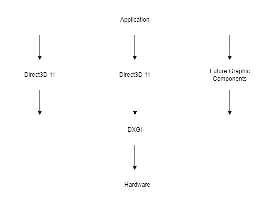
DirectX Graphics Infrastructure (DXGI)
The DirectX Graphics Infrastructure is a component that lies at the base of all the most recent versions of Direct3D. Its job is to handle fundamental tasks such as displaying images on the screen and finding out what resolutions the monitor and video card can handle.
DXGI is not actually a part of Direct3D. It underlies it and other graphics components, and it acts as an interface between Direct3D and the hardware.
Adapter
An Adapter provides information on the physical properties of a given DirectX device. You can query your current GPU’s name, manufacturer, how much memory it has, and much more.
// 👋 Declare Handles
IDXGIAdapter1* adapter;

// 🔌 Create Adapter
for (UINT adapterIndex = 0;
     DXGI_ERROR_NOT_FOUND != factory->EnumAdapters1(adapterIndex, &adapter);
     ++adapterIndex)
{
    DXGI_ADAPTER_DESC1 desc;
    adapter->GetDesc1(&desc);

    // ❌ Don't select the Basic Render Driver adapter.
    if (desc.Flags & DXGI_ADAPTER_FLAG_SOFTWARE)
    {
        continue;
    }

    // ✔️ Check if the adapter supports Direct3D 12, and use that for the rest
    // of the application
    if (SUCCEEDED(D3D12CreateDevice(adapter, D3D_FEATURE_LEVEL_12_0,
                                    _uuidof(ID3D12Device), nullptr)))
    {
        break;
    }

    // ❌ Else we won't use this iteration's adapter, so release it
    adapter->Release();
}
Device
The device is represented by the ID3D12Device interface. The device is a virtual adapter which we use to create command lists, pipeline state objects, root signatures, command allocators, command queues, fences, resources, descriptors and descriptor heaps. Once we find the adapter index we want to use, we create a device by calling D3D12CreateDevice().
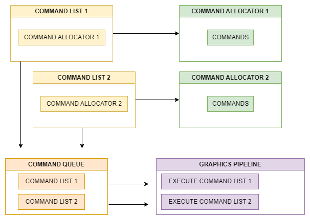
Command Queues
Command Queues are represented by the ID3D12CommandQueue interface, and created with the CreateCommandQueue() method of the device interface. We use the command queue to submit Command Lists to be executed by the GPU.
Command Allocators
Command Allocators are represented by the ID3D12CommandAllocator interface, and created with the CreateCommandAllocator () method of the device interface.
Command Allocators represent the GPU memory that commands from Command Lists and Bundles are stored in.
Synchronization
DirectX 12 features a number of synchronization primitives that can help the driver know how resources will be used in the future, know when tasks have been completed by the GPU, etc.
A Fence lets your program know when certain tasks have been executed by the GPU, be it uploads to GPU exclusive memory, or when you’ve finished presenting to the screen.
// Declare handles
UINT frameIndex;
HANDLE fenceEvent;
ID3D12Fence* fence;
UINT64 fenceValue;

// Create fence
ThrowIfFailed(device->CreateFence(0, D3D12_FENCE_FLAG_NONE,
                                  IID_PPV_ARGS(&fence)));
A Barrier lets the driver know how a resource should be used in upcoming commands. This can be useful if say, you’re writing to a texture, and you want to copy that texture to another texture (such as the swapchain’s render attachment).
// Declare handles
ID3D12GraphicsCommandList* commandList;
// Create Barrier
D3D12_RESOURCE_BARRIER barrier = {};
barrier.Type = D3D12_RESOURCE_BARRIER_TYPE_TRANSITION;
barrier.Flags = D3D12_RESOURCE_BARRIER_FLAG_NONE;
barrier.Transition.pResource = texResource;
barrier.Transition.StateBefore = D3D12_RESOURCE_STATE_COPY_SOURCE;
barrier.Transition.StateAfter = D3D12_RESOURCE_STATE_UNORDERED_ACCESS;
barrier.Transition.Subresource = D3D12_RESOURCE_BARRIER_ALL_SUBRESOURCES;
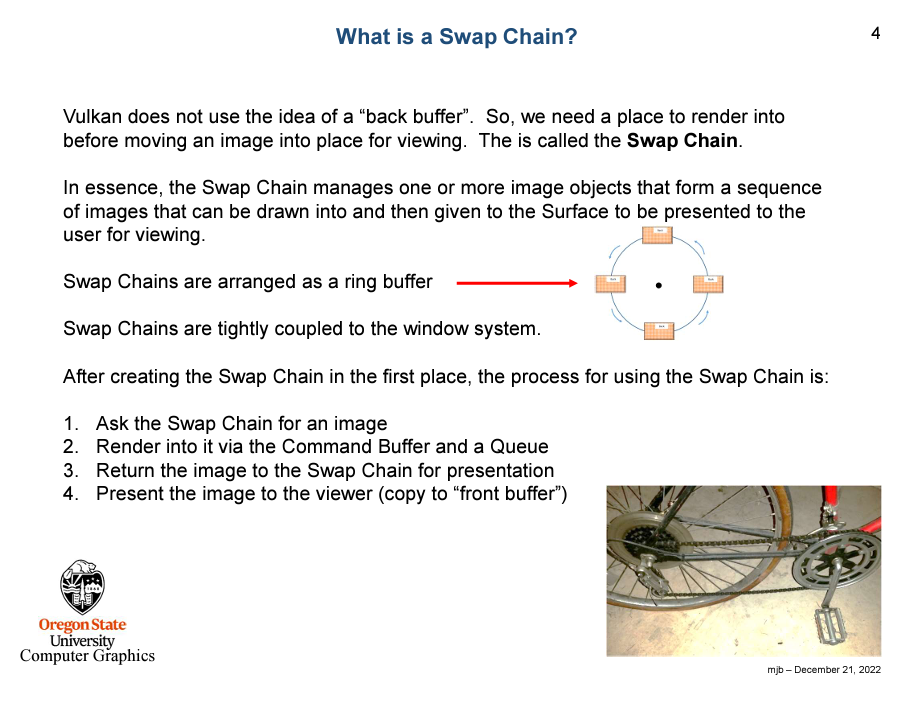
commandList->ResourceBarrier(1, &barrier);Swapchain
Swapchains handle swapping and allocating back buffers to display what you’re rendering to a given window. The concept is the same as Vulkan.
Graphic Pipeline
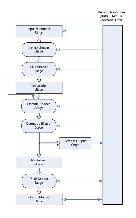
Here is the fun part if you understand each terms and the flow means in the graphic pipeline, especially resouces part. Otherwise, it’s like reading some foreign language books, which will waste you lots of time. I would like to start with the overview from Microsoft website
A graphics pipeline is the sequential flow of data inputs and outputs as the GPU renders frames. Given the pipeline state and inputs, the GPU performs a series of operations to create the resulting images. A graphics pipeline contains shaders, which perform programmable rendering effects and calculations, and fixed function operations.
I would like to refer the tutorial website from Braynzar Soft for explaination.
Shader Stage
Input Assembler (IA)
The first stage of the graphics pipeline is called the Input Assembler (IA) Stage. This is a fixed function stage, which means we do not do the programming to implement it. Instead, we instruct the device to configure the IA so that it knows how to create the geometric primitives like triangles, lines or points from the data we give it in the form of buffers containing vertex and index data. We provide an Input Layout to the IA so that it knows how to read the vertex data.
D3D12_INPUT_ELEMENT_DESC layout[] =
{
    { "POSITION", 0, DXGI_FORMAT_R32G32B32_FLOAT, 0, 0, D3D12_INPUT_PER_VERTEX_DATA, 0 },
};
Vertex Shader (VS)
The VS Stage is what ALL the vertices have to go through. With the VS, you are able to do things like transformation, scaling, lighting, displacement mapping for textures and stuff like that.
float4 main(float4 pos : POSITION) : SV_POSITION
{
    return pos;
}
Tessellation Stages
The Tesselation Stages include the Hull Shader, Tessellator, and the Domain Shader stages. They all work together to implement something called tesselation. What tesselation does, is take a primitive object, such as a triangle or line, and divide it up into many smaller sections to increase the detail of models, and extremely fast. It creates all these new primitives on the GPU before they are put onto the screen, and they are not saved to memory, so this saves a lot of time than creating them on the CPU where they would need to be stored in memory.
Hull Shader (HS)
The Hull Shader (HS) stage is one of the tessellation stages, which efficiently break up a single surface of a model into many triangles. The Hull Shader (HS) stage produces a geometry patch (and patch constants) that correspond to each input patch (quad, triangle, or line).
Tessellator (TS)
The Tessellator (TS) stage creates a sampling pattern of the domain that represents the geometry patch and generates a set of smaller objects (triangles, points, or lines) that connect these samples.
Domain Shader (DS)
This is the third of three stages in the tessellation process. The Domain Shader (DS) stage calculates the vertex position of a subdivided point in the output patch; it calculates the vertex position that corresponds to each domain sample.
Geometry Shader (GS)
The Geometry Shader (GS) stage processes entire primitives: triangles, lines, and points, along with their adjacent vertices. It is useful for algorithms including Point Sprite Expansion, Dynamic Particle Systems, and Shadow Volume Generation. It supports geometry amplification and de-amplification.
Rasterizer (RS)
The rasterizer clips primitives that aren’t in view, prepares primitives for the Pixel Shader (PS) stage, and determines how to invoke pixel shaders. The rasterization stage converts vector information (composed of shapes or primitives) into a raster image (composed of pixels) for the purpose of displaying real-time 3D graphics.
Pixel Shader (PS)
The Pixel Shader (PS) stage receives interpolated data for a primitive, and generates per-pixel data such as color. The Pixel Shader (PS) stage enables rich shading techniques such as per-pixel lighting and post-processing. A pixel shader is a program that combines constant variables, texture data, interpolated per-vertex values, and other data to produce per-pixel outputs.
float4 main() : SV_TARGET
{
    return float4(1.0f, 1.0f, 1.0f, 1.0f);
}
Output Merger (OM)
The final Stage in the Pipeline is the Output Merger Stage. Basically this stage takes the pixel fragments and depth/stencil buffers and determines which pixels are actually written to the render target. It also applies blending based on the blend model and blend factor we set.
Add Resources
 We have explain data flow in the graphic pipeline. Now we need to prepare the data feeding inside it. It looks scary, huh? I will try to break them down piece by piece, like doing the bottom-up. Eventually, every resouces will attach to our graphic pipeline.
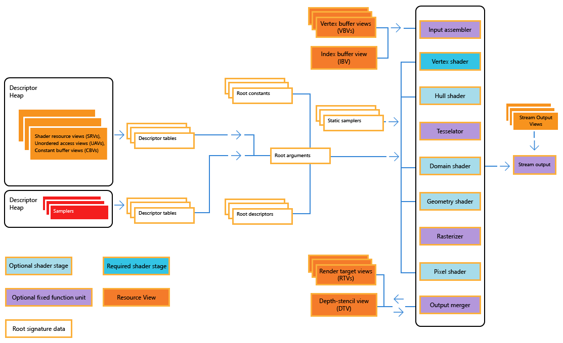
Root Signature
Among all of the resouces, I think root signature is the most confusing one since the naming doesn’t show any clue what is this for. Here is the short defintion from Microsoft:
The root signature defines what types of resources are bound to the graphics pipeline.
A root signature is similar to an API function signature, it determines the types of data the shaders should expect, but does not define the actual memory or data. A root parameter is one entry in the root signature. The actual values of root parameters set and changed at runtime are called root arguments. Changing the root arguments changes the data that the shaders read.
TL;DR
- Root Signatures define the data (resources) that shaders access.
- Root signatures are like a parameter list for a function, where the function is the shaders, and the parameter list is the type of data the shaders access.
- Root arguments are the actual values of root parameters set and changed at runtime
Root constants descriptor and tables
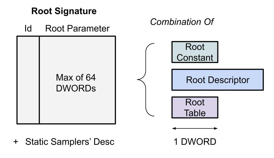
Root signatures contain Root Constants, Root Descriptors, and Descriptor Tables. A Root Parameter is one entry, being either a root constant, root descriptor, or descriptor table, into the root signature.
Here is the explaination:
- Root Constants: Root Constants are inline 32-bit values (they cost 1 DWORD). These values are stored directly inside the root signature. Because memory is limited for root signatures, you want to store only the most often changed constant values shaders access here. These values show up as a constant buffer to shaders. There is no cost to access these variables from shaders (no redirection), so accessing them is very fast.
- Root Descriptors: Root Descriptors are inlined descriptors that are accessed most often by the shaders. These are 64-bit virtual addresses (2 DWORDs). These descriptors are limited to CBV’s and raw or structured SRV’s and UAV’s. Complex types like Texture2D SRV’s cannot be used. There is a cost of one redirection when referencing Root Descriptors from shaders. Another thing to note about Root Descriptors, is they are only a pointer to the resource, they do not include a size of the data, which means there can be no out of bounds checking when accessing resources from root descriptors, unlike descriptors stored in a descriptor heap, which do include a size, and where out of bounds checking can be done.
- Descriptor Tables: Descriptor Tables are an offset and a length into a descriptor heap. Descriptor tables are only 32-bits (1 DWORD). There is no limit to how many descriptors are inside a descriptor table (except indirectly the number of descriptors that can fit in the maximum allowed descriptor heap size). There is a cost of two indirections when accessing resources from a descriptor table. The first indirection is from the descriptor table pointer to the descriptor stored in the heap, then from the descriptor heap to the actual resource.
Overall, the root signature should be a data structure like this:
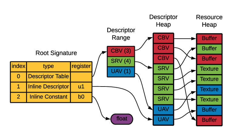
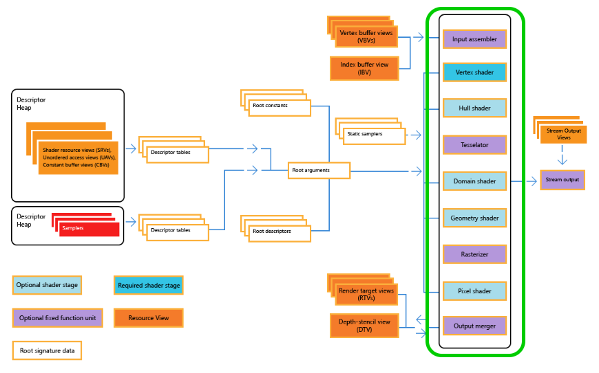
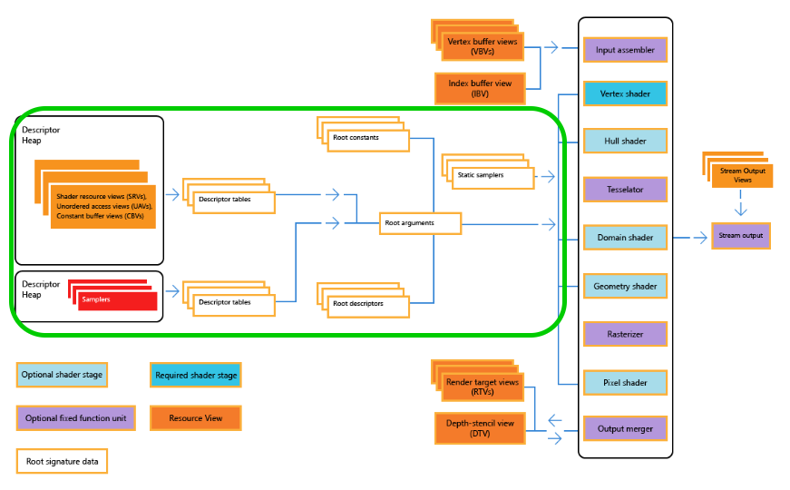
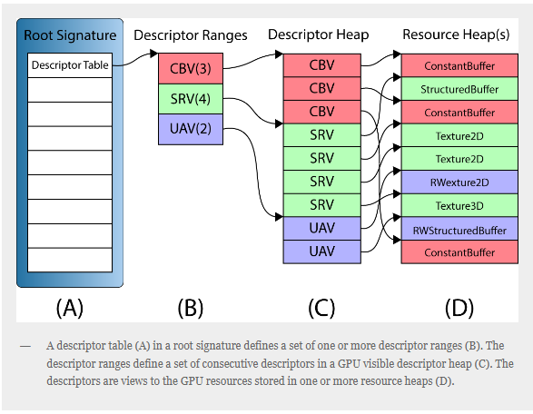
Descriptor Heap
Descriptor Heaps are a list of descriptors. They are a chunk of memory where the descriptors are stored. Descriptor Heaps are represented by the interface ID3D12DescriptorHeap and are created with the method ID3D12Device::CreateDescriptorHeap().
What is Descriptor?
A descriptor is a relatively small block of data that fully describes an object to the GPU, in a GPU-specific opaque format. There are several different types of descriptors—render target views (RTVs), depth stencil views (DSVs), shader resource views (SRVs), unordered access views (UAVs), constant buffer views (CBVs), and samplers. We will talk about them one by one.
What does view mean?
The term “view” is used to mean “data in the required format”. For example, a Constant Buffer View (CBV) would be constant buffer data correctly formatted.
- Render target view (RTV): Render targets enable a scene to be rendered to a temporary intermediate buffer, rather than to the back buffer to be rendered to the screen.
- Depth stencil view (DSV): A depth stencil view provides the format and buffer for holding depth and stencil information. The depth buffer is used to cull the drawing of pixels that would be invisible to the viewer as they are occluded from view by a closer object. The stencil buffer can be used to cull all drawing outside of a defined shape.
- Shader resource view (SRV) and Unordered Access view (UAV): Shader resource views typically wrap textures in a format that the shaders can access them. An unordered access view provides similar functionality, but enables the reading and writing to the texture (or other resource) in any order.
- Constant buffer view (CBV): Constant buffers contain shader constant data. The value of them is that the data persists, and can be accessed by any GPU shader, until it is necessary to change the data. (such as world, projection and view matrices, which remain constant throughout the drawing of one frame.)
- Sampler: Sampling is the process of reading input values from a texture, or other resource. A “sampler” is any object that reads from resources.
Buffer
I would like to borrow the code from alain for the remaining part. Apologize for my laziness.
A buffer resource is a collection of fully typed data, grouped into elements. Buffers store data, such as texture coordinates in a vertex buffer, indexes in an index buffer, shader constants data in a constant buffer, position vectors, normal vectors, or device state.
Vertex Buffer
A vertex buffer contains the vertex data used to define your geometry. Vertex data includes position coordinates, color data, texture coordinate data, normal data, and so on.
The simplest example of a vertex buffer is one that only contains position data. like this:

An example of this could be a vertex buffer that contains per-vertex position, normal and texture coordinates. Like this:
This vertex buffer contains per-vertex data; each vertex stores three elements (position, normal, and texture coordinates). The position and normal are each typically specified using three 32-bit floats and the texture coordinates using two 32-bit floats.
Before you create a vertex buffer, you need to define its layout. After the input-layout object is created, you bind it to the Input Assembler (IA) stage.
// 💾 Declare Data
struct Vertex
{
    float position[3];
    float color[3];
};

Vertex vertexBufferData[3] = {{{1.0f, -1.0f, 0.0f}, {1.0f, 0.0f, 0.0f}},
                              {{-1.0f, -1.0f, 0.0f}, {0.0f, 1.0f, 0.0f}},
                              {{0.0f, 1.0f, 0.0f}, {0.0f, 0.0f, 1.0f}}};

// 👋 Declare Handles
ID3D12Resource* vertexBuffer;
D3D12_VERTEX_BUFFER_VIEW vertexBufferView;

const UINT vertexBufferSize = sizeof(vertexBufferData);

D3D12_HEAP_PROPERTIES heapProps;
heapProps.Type = D3D12_HEAP_TYPE_UPLOAD;
heapProps.CPUPageProperty = D3D12_CPU_PAGE_PROPERTY_UNKNOWN;
heapProps.MemoryPoolPreference = D3D12_MEMORY_POOL_UNKNOWN;
heapProps.CreationNodeMask = 1;
heapProps.VisibleNodeMask = 1;

D3D12_RESOURCE_DESC vertexBufferResourceDesc;
vertexBufferResourceDesc.Dimension = D3D12_RESOURCE_DIMENSION_BUFFER;
vertexBufferResourceDesc.Alignment = 0;
vertexBufferResourceDesc.Width = vertexBufferSize;
vertexBufferResourceDesc.Height = 1;
vertexBufferResourceDesc.DepthOrArraySize = 1;
vertexBufferResourceDesc.MipLevels = 1;
vertexBufferResourceDesc.Format = DXGI_FORMAT_UNKNOWN;
vertexBufferResourceDesc.SampleDesc.Count = 1;
vertexBufferResourceDesc.SampleDesc.Quality = 0;
vertexBufferResourceDesc.Layout = D3D12_TEXTURE_LAYOUT_ROW_MAJOR;
vertexBufferResourceDesc.Flags = D3D12_RESOURCE_FLAG_NONE;

ThrowIfFailed(device->CreateCommittedResource(
    &heapProps, D3D12_HEAP_FLAG_NONE, &vertexBufferResourceDesc,
    D3D12_RESOURCE_STATE_GENERIC_READ, nullptr, IID_PPV_ARGS(&vertexBuffer)));

// 📄 Copy the triangle data to the vertex buffer.
UINT8* pVertexDataBegin;

// 🙈 We do not intend to read from this resource on the CPU.
D3D12_RANGE readRange;
readRange.Begin = 0;
readRange.End = 0;

ThrowIfFailed(vertexBuffer->Map(0, &readRange,
                                reinterpret_cast<void**>(&pVertexDataBegin)));
memcpy(pVertexDataBegin, vertexBufferData, sizeof(vertexBufferData));
vertexBuffer->Unmap(0, nullptr);

// 👀 Initialize the vertex buffer view.
vertexBufferView.BufferLocation = vertexBuffer->GetGPUVirtualAddress();
vertexBufferView.StrideInBytes = sizeof(Vertex);
vertexBufferView.SizeInBytes = vertexBufferSize;
Index Buffer View
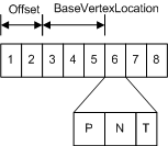
Index buffers contain integer offsets into vertex buffers and are used to render primitives more efficiently. An index buffer contains a sequential set of 16-bit or 32-bit indices; each index is used to identify a vertex in a vertex buffer. An index buffer can be visualized like the following illustration.
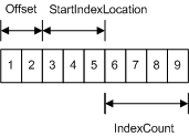 The sequential indices stored in an index buffer are located with the following parameters:
- Offset - the number of bytes from the base address of the index buffer.
- StartIndexLocation - specifies the first index buffer element from the base address and the offset. The start location represents the first index to render.
- IndexCount - the number of indices to render.
Start of Index Buffer = Index Buffer Base Address + Offset (bytes) + StartIndexLocation * ElementSize (bytes);// 💾 Declare Data
uint32_t indexBufferData[3] = {0, 1, 2};
// 👋 Declare Handles
ID3D12Resource* indexBuffer;
D3D12_INDEX_BUFFER_VIEW indexBufferView;
const UINT indexBufferSize = sizeof(indexBufferData);
D3D12_HEAP_PROPERTIES heapProps;
heapProps.Type = D3D12_HEAP_TYPE_UPLOAD;
heapProps.CPUPageProperty = D3D12_CPU_PAGE_PROPERTY_UNKNOWN;
heapProps.MemoryPoolPreference = D3D12_MEMORY_POOL_UNKNOWN;
heapProps.CreationNodeMask = 1;
heapProps.VisibleNodeMask = 1;
D3D12_RESOURCE_DESC vertexBufferResourceDesc;
vertexBufferResourceDesc.Dimension = D3D12_RESOURCE_DIMENSION_BUFFER;
vertexBufferResourceDesc.Alignment = 0;
vertexBufferResourceDesc.Width = indexBufferSize;
vertexBufferResourceDesc.Height = 1;
vertexBufferResourceDesc.DepthOrArraySize = 1;
vertexBufferResourceDesc.MipLevels = 1;
vertexBufferResourceDesc.Format = DXGI_FORMAT_UNKNOWN;
vertexBufferResourceDesc.SampleDesc.Count = 1;
vertexBufferResourceDesc.SampleDesc.Quality = 0;
vertexBufferResourceDesc.Layout = D3D12_TEXTURE_LAYOUT_ROW_MAJOR;
vertexBufferResourceDesc.Flags = D3D12_RESOURCE_FLAG_NONE;
ThrowIfFailed(device->CreateCommittedResource(
&heapProps, D3D12_HEAP_FLAG_NONE, &vertexBufferResourceDesc,
D3D12_RESOURCE_STATE_GENERIC_READ, nullptr, IID_PPV_ARGS(&indexBuffer)));
// 📄 Copy data to DirectX 12 driver memory:
UINT8* pVertexDataBegin;
// 🙈 We do not intend to read from this resource on the CPU.
D3D12_RANGE readRange;
readRange.Begin = 0;
readRange.End = 0;
ThrowIfFailed(indexBuffer->Map(0, &readRange,
reinterpret_cast<void**>(&pVertexDataBegin)));
memcpy(pVertexDataBegin, indexBufferData, sizeof(indexBufferData));
indexBuffer->Unmap(0, nullptr);
// 👀 Initialize the index buffer view.
indexBufferView.BufferLocation = indexBuffer->GetGPUVirtualAddress();
indexBufferView.Format = DXGI_FORMAT_R32_UINT;
indexBufferView.SizeInBytes = indexBufferSize;Constant Buffer View
I knew we mentioned it previously but we need to state it again here. A constant buffer allows you to efficiently supply shader constants data to the pipeline. You can use a constant buffer to store the results of the stream-output stage. Conceptually, a constant buffer looks just like a single-element vertex buffer, as shown in the following illustration.

// 💾 Declare Data
struct
{
    glm::mat4 projectionMatrix;
    glm::mat4 modelMatrix;
    glm::mat4 viewMatrix;
} cbVS;

// 👋 Declare Handles
ID3D12Resource* constantBuffer;
ID3D12DescriptorHeap* constantBufferHeap;
UINT8* mappedConstantBuffer;

// 🧊 Create the Constant Buffer

D3D12_HEAP_PROPERTIES heapProps;
heapProps.Type = D3D12_HEAP_TYPE_UPLOAD;
heapProps.CPUPageProperty = D3D12_CPU_PAGE_PROPERTY_UNKNOWN;
heapProps.MemoryPoolPreference = D3D12_MEMORY_POOL_UNKNOWN;
heapProps.CreationNodeMask = 1;
heapProps.VisibleNodeMask = 1;

D3D12_DESCRIPTOR_HEAP_DESC heapDesc = {};
heapDesc.NumDescriptors = 1;
heapDesc.Flags = D3D12_DESCRIPTOR_HEAP_FLAG_SHADER_VISIBLE;
heapDesc.Type = D3D12_DESCRIPTOR_HEAP_TYPE_CBV_SRV_UAV;
ThrowIfFailed(device->CreateDescriptorHeap(&heapDesc,
                                           IID_PPV_ARGS(&constantBufferHeap)));

D3D12_RESOURCE_DESC cbResourceDesc;
cbResourceDesc.Dimension = D3D12_RESOURCE_DIMENSION_BUFFER;
cbResourceDesc.Alignment = 0;
cbResourceDesc.Width = (sizeof(cbVS) + 255) & ~255;
cbResourceDesc.Height = 1;
cbResourceDesc.DepthOrArraySize = 1;
cbResourceDesc.MipLevels = 1;
cbResourceDesc.Format = DXGI_FORMAT_UNKNOWN;
cbResourceDesc.SampleDesc.Count = 1;
cbResourceDesc.SampleDesc.Quality = 0;
cbResourceDesc.Layout = D3D12_TEXTURE_LAYOUT_ROW_MAJOR;
cbResourceDesc.Flags = D3D12_RESOURCE_FLAG_NONE;

ThrowIfFailed(device->CreateCommittedResource(
    &heapProps, D3D12_HEAP_FLAG_NONE, &cbResourceDesc,
    D3D12_RESOURCE_STATE_GENERIC_READ, nullptr, IID_PPV_ARGS(&constantBuffer)));
constantBufferHeap->SetName(L"Constant Buffer Upload Resource Heap");

// 👓 Create our Constant Buffer View
D3D12_CONSTANT_BUFFER_VIEW_DESC cbvDesc = {};
cbvDesc.BufferLocation = constantBuffer->GetGPUVirtualAddress();
cbvDesc.SizeInBytes =
    (sizeof(cbVS) + 255) & ~255; // CB size is required to be 256-byte aligned.

D3D12_CPU_DESCRIPTOR_HANDLE
    cbvHandle(constantBufferHeap->GetCPUDescriptorHandleForHeapStart());
cbvHandle.ptr = cbvHandle.ptr + device->GetDescriptorHandleIncrementSize(
                                    D3D12_DESCRIPTOR_HEAP_TYPE_CBV_SRV_UAV) *
                                    0;

device->CreateConstantBufferView(&cbvDesc, cbvHandle);

// 🙈 We do not intend to read from this resource on the CPU.
D3D12_RANGE readRange;
readRange.Begin = 0;
readRange.End = 0;

ThrowIfFailed(constantBuffer->Map(
    0, &readRange, reinterpret_cast<void**>(&mappedConstantBuffer)));
memcpy(mappedConstantBuffer, &cbVS, sizeof(cbVS));
constantBuffer->Unmap(0, &readRange);
Shader
Vertex Shader
cbuffer cb : register(b0)
{
    row_major float4x4 projectionMatrix : packoffset(c0);
    row_major float4x4 modelMatrix : packoffset(c4);
    row_major float4x4 viewMatrix : packoffset(c8);
};

struct VertexInput
{
    float3 inPos : POSITION;
    float3 inColor : COLOR;
};

struct VertexOutput
{
    float3 color : COLOR;
    float4 position : SV_Position;
};

VertexOutput main(VertexInput vertexInput)
{
    float3 inColor = vertexInput.inColor;
    float3 inPos = vertexInput.inPos;
    float3 outColor = inColor;
    float4 position = mul(float4(inPos, 1.0f), mul(modelMatrix, mul(viewMatrix, projectionMatrix)));

    VertexOutput output;
    output.position = position;
    output.color = outColor;
    return output;
}
Pixel Shader
struct PixelInput
{
float3 color : COLOR;
};
struct PixelOutput
{
float4 attachment0 : SV_Target0;
};
PixelOutput main(PixelInput pixelInput)
{
float3 inColor = pixelInput.color;
PixelOutput output;
output.attachment0 = float4(inColor, 1.0f);
return output;
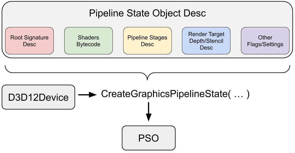
}Pipeline State Object
The PSO is an object that represents the settings for our graphics device (GPU) in order to draw or dispatch something. Now is the time to stick everything together.
// 👋 Declare handles
ID3D12PipelineState* pipelineState;

// ⚗️ Define the Graphics Pipeline
D3D12_GRAPHICS_PIPELINE_STATE_DESC psoDesc = {};

// 🔣 Input Assembly
D3D12_INPUT_ELEMENT_DESC inputElementDescs[] = {
    {"POSITION", 0, DXGI_FORMAT_R32G32B32_FLOAT, 0, 0,
     D3D12_INPUT_CLASSIFICATION_PER_VERTEX_DATA, 0},
    {"COLOR", 0, DXGI_FORMAT_R32G32B32_FLOAT, 0, 12,
     D3D12_INPUT_CLASSIFICATION_PER_VERTEX_DATA, 0}};
psoDesc.InputLayout = {inputElementDescs, _countof(inputElementDescs)};

// 🦄 Resources
psoDesc.pRootSignature = rootSignature;

// 🔺 Vertex Shader
D3D12_SHADER_BYTECODE vsBytecode;
vsBytecode.pShaderBytecode = vertexShaderBlob->GetBufferPointer();
vsBytecode.BytecodeLength = vertexShaderBlob->GetBufferSize();
psoDesc.VS = vsBytecode;

// 🖌️ Pixel Shader
D3D12_SHADER_BYTECODE psBytecode;
psBytecode.pShaderBytecode = pixelShaderBlob->GetBufferPointer();
psBytecode.BytecodeLength = pixelShaderBlob->GetBufferSize();
psoDesc.PS = psBytecode;

// 🟨 Rasterization
D3D12_RASTERIZER_DESC rasterDesc;
rasterDesc.FillMode = D3D12_FILL_MODE_SOLID;
rasterDesc.CullMode = D3D12_CULL_MODE_NONE;
rasterDesc.FrontCounterClockwise = FALSE;
rasterDesc.DepthBias = D3D12_DEFAULT_DEPTH_BIAS;
rasterDesc.DepthBiasClamp = D3D12_DEFAULT_DEPTH_BIAS_CLAMP;
rasterDesc.SlopeScaledDepthBias = D3D12_DEFAULT_SLOPE_SCALED_DEPTH_BIAS;
rasterDesc.DepthClipEnable = TRUE;
rasterDesc.MultisampleEnable = FALSE;
rasterDesc.AntialiasedLineEnable = FALSE;
rasterDesc.ForcedSampleCount = 0;
rasterDesc.ConservativeRaster = D3D12_CONSERVATIVE_RASTERIZATION_MODE_OFF;
psoDesc.RasterizerState = rasterDesc;
psoDesc.PrimitiveTopologyType = D3D12_PRIMITIVE_TOPOLOGY_TYPE_TRIANGLE;

// 🌀 Color/Blend
D3D12_BLEND_DESC blendDesc;
blendDesc.AlphaToCoverageEnable = FALSE;
blendDesc.IndependentBlendEnable = FALSE;
const D3D12_RENDER_TARGET_BLEND_DESC defaultRenderTargetBlendDesc = {
    FALSE,
    FALSE,
    D3D12_BLEND_ONE,
    D3D12_BLEND_ZERO,
    D3D12_BLEND_OP_ADD,
    D3D12_BLEND_ONE,
    D3D12_BLEND_ZERO,
    D3D12_BLEND_OP_ADD,
    D3D12_LOGIC_OP_NOOP,
    D3D12_COLOR_WRITE_ENABLE_ALL,
};
for (UINT i = 0; i < D3D12_SIMULTANEOUS_RENDER_TARGET_COUNT; ++i)
    blendDesc.RenderTarget[i] = defaultRenderTargetBlendDesc;
psoDesc.BlendState = blendDesc;

// 🌑 Depth/Stencil State
psoDesc.DepthStencilState.DepthEnable = FALSE;
psoDesc.DepthStencilState.StencilEnable = FALSE;
psoDesc.SampleMask = UINT_MAX;

// 🖼️ Output
psoDesc.NumRenderTargets = 1;
psoDesc.RTVFormats[0] = DXGI_FORMAT_R8G8B8A8_UNORM;
psoDesc.SampleDesc.Count = 1;

// 🌟 Create the raster pipeline state
try
{
    ThrowIfFailed(device->CreateGraphicsPipelineState(
        &psoDesc, IID_PPV_ARGS(&pipelineState)));
}
catch (std::exception e)
{
    std::cout << "Failed to create Graphics Pipeline!";
}
Setup Commands
We have the pipeline state. Now we need to set up our command list to lunch the draw. Before that, the command list need to know the resources location, Rasterization setting, and configure the barriers.
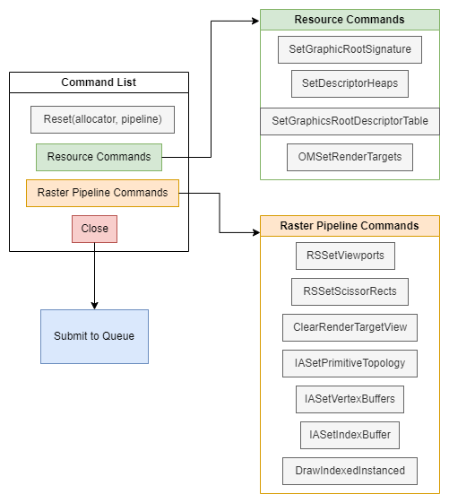
I would like to borrow Alain’s code again since he seperate every step super clear.
// 👋 Declare handles
ID3D12CommandAllocator* commandAllocator;
ID3D12PipelineState* initialPipelineState;
ID3D12GraphicsCommandList* commandList;

// 📃 Create the command list.
ThrowIfFailed(device->CreateCommandList(0, D3D12_COMMAND_LIST_TYPE_DIRECT,
                                        commandAllocator, initialPipelineState,
                                        IID_PPV_ARGS(&commandList)));


// Encode those commands and submit them

// 🚿 Reset the command list and add new commands.
ThrowIfFailed(commandAllocator->Reset());

// 🖌️ Begin using the Raster Graphics Pipeline
ThrowIfFailed(commandList->Reset(commandAllocator, pipelineState));

// 🔳 Setup Resources
commandList->SetGraphicsRootSignature(rootSignature);
ID3D12DescriptorHeap* pDescriptorHeaps[] = {constantBufferHeap};
commandList->SetDescriptorHeaps(_countof(pDescriptorHeaps), pDescriptorHeaps);
D3D12_GPU_DESCRIPTOR_HANDLE
    cbvHandle(constantBufferHeap->GetGPUDescriptorHandleForHeapStart());
commandList->SetGraphicsRootDescriptorTable(0, cbvHandle);

// 🖼️ Indicate that the back buffer will be used as a render target.
D3D12_RESOURCE_BARRIER renderTargetBarrier;
renderTargetBarrier.Type = D3D12_RESOURCE_BARRIER_TYPE_TRANSITION;
renderTargetBarrier.Flags = D3D12_RESOURCE_BARRIER_FLAG_NONE;
renderTargetBarrier.Transition.pResource = renderTargets[frameIndex];
renderTargetBarrier.Transition.StateBefore = D3D12_RESOURCE_STATE_PRESENT;
renderTargetBarrier.Transition.StateAfter = D3D12_RESOURCE_STATE_RENDER_TARGET;
renderTargetBarrier.Transition.Subresource =
    D3D12_RESOURCE_BARRIER_ALL_SUBRESOURCES;
commandList->ResourceBarrier(1, &renderTargetBarrier);

D3D12_CPU_DESCRIPTOR_HANDLE
    rtvHandle(rtvHeap->GetCPUDescriptorHandleForHeapStart());
rtvHandle.ptr = rtvHandle.ptr + (frameIndex * rtvDescriptorSize);
commandList->OMSetRenderTargets(1, &rtvHandle, FALSE, nullptr);

// 🎥 Record raster commands.
const float clearColor[] = {0.2f, 0.2f, 0.2f, 1.0f};
commandList->RSSetViewports(1, &viewport);
commandList->RSSetScissorRects(1, &surfaceSize);
commandList->ClearRenderTargetView(rtvHandle, clearColor, 0, nullptr);
commandList->IASetPrimitiveTopology(D3D_PRIMITIVE_TOPOLOGY_TRIANGLELIST);
commandList->IASetVertexBuffers(0, 1, &vertexBufferView);
commandList->IASetIndexBuffer(&indexBufferView);

commandList->DrawIndexedInstanced(3, 1, 0, 0, 0);

// 🖼️ Indicate that the back buffer will now be used to present.
D3D12_RESOURCE_BARRIER presentBarrier;
presentBarrier.Type = D3D12_RESOURCE_BARRIER_TYPE_TRANSITION;
presentBarrier.Flags = D3D12_RESOURCE_BARRIER_FLAG_NONE;
presentBarrier.Transition.pResource = renderTargets[frameIndex];
presentBarrier.Transition.StateBefore = D3D12_RESOURCE_STATE_RENDER_TARGET;
presentBarrier.Transition.StateAfter = D3D12_RESOURCE_STATE_PRESENT;
presentBarrier.Transition.Subresource = D3D12_RESOURCE_BARRIER_ALL_SUBRESOURCES;

commandList->ResourceBarrier(1, &presentBarrier);

ThrowIfFailed(commandList->Close());
Render
Finally, we make it here. Render in DirectX 12 is super easy. It’s much similiar like OpenGL. The flow is like:
- Do some update
- Submit your command lists to be executed
- Present the swapchain to windows
- Signal your application you have done