Vulkan Introduction
Vulkan Introduction
The content is based on the awesome tutorial website from Alexander Overvoorde
What we need to draw a triangle?
Window
Vulkan is a platform agnostic API. It can not interface directly with the window system on its own. To establish the connection between Vulkan and the window system to present results to the screen, we need to use the WSI (Window System Integration) extensions. A VkSurfaceKHR object represents an abstract type of surface to present rendered images to.
Instance
The instance is the connection between your application and the Vulkan library and creating it involves specifying some details about your application to the driver.
Validation Layers
Validation layers are optional components that hook into Vulkan function calls to apply additional operations. Common operations in validation layers are:
- Checking the values of parameters against the specification to detect misuse
- Tracking creation and destruction of objects to find resource leaks
- Checking thread safety by tracking the threads that calls originate from
- Logging every call and its parameters to the standard output Tracing Vulkan calls for profiling and replaying
Physical Devices
Select a graphics card in the system that supports the features we need. To evaluate the suitability of a device we can start by querying for some details. Basic device properties like the name, type and supported Vulkan version can be queried using vkGetPhysicalDeviceProperties
Queue Family
Anything from drawing to uploading textures, requires commands to be submitted to a queue. There are different types of queues that originate from different queue families and each family of queues allows only a subset of commands.
Logical Devices
After selecting a physical device to use we need to set up a logical device to interface with it.
Windows
Since Vulkan is a platform agnostic API, it can not interface directly with the window system on its own. To establish the connection between Vulkan and the window system to present results to the screen, we need to use the WSI (Window System Integration) extensions.
Swap chain
Vulkan requires an infrastructure that will own the buffers we will render to before we visualize them on the screen. This infrastructure is known as the swap chain and must be created explicitly in Vulkan. The swap chain is essentially a queue of images (VkImage) that are waiting to be presented to the screen.
Image Views
To use any VkImage, including those in the swap chain, in the render we have to create a VkImageView object. An image view is quite literally a view into an image. It describes how to access the image and which part of the image to access
Graphic Pipeline
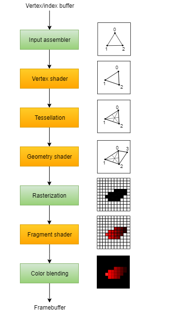 Stages with a green color are known as fixed-function stages. These stages allow you to tweak their operations using parameters, but the way they work is predefined.
Stages with an orange color on the other hand are programmable, which means that you can upload your own code to the graphics card to apply exactly the operations you want.
Pipeline
The VkPipeline is a huge object in Vulkan that encompasses the configuration of the entire GPU for the draw. Building them can be very expensive, as it will fully convert the shader module into the GPU instructions, and will validate the setup for it.
Vulkan pipelines are a massive object with many different configuration structs, some of them even running pointers and being arrays.
- Pipelines (often called “pipeline state objects”) are used to bake all states that affect a pipeline
- While in OpenGL every state can be changed at (almost) any time, Vulkan requires to layout the graphics (and compute) pipeline states upfront
- So for each combination of non-dynamic pipeline states you need a new pipeline (there are a few exceptions to this not discussed here)
- Even though this adds a new dimension of planning ahead, it’s a great opportunity for performance optimizations by the driver
Pipeline Layout
Pipeline layouts contain the information about shader inputs of a given pipeline. It’s here where you would configure your push-constants and descriptor sets.
- The pipeline layout is used by a pipeline to access the descriptor sets
- It defines interface (without binding any actual data) between the shader stages used by the pipeline and the shader resources
- A pipeline layout can be shared among multiple pipelines as long as their interfaces match
Shader Modules
- Vertex Shader
- Fragment Shader
Fixed function
- Dynamic state
- Vertex input
- Input assembly
- Viewports and scissors
- Rasterizer
- Multisampling
- Depth and stencil testing
- Color blending
- Pipeline layout
Render Passes
Before we can finish creating the pipeline, we need to tell Vulkan about the framebuffer attachments that will be used while rendering. We need to specify how many color and depth buffers there will be, how many samples to use for each of them and how their contents should be handled throughout the rendering operations. All of this information is wrapped in a render pass object
- Render passes are a new concept in Vulkan. They describe the attachments used during rendering and may contain multiple subpasses with attachment dependencies
- This allows the driver to know up-front what the rendering will look like and is a good opportunity to optimize especially on tile-based renderers (with multiple subpasses)
- Using sub pass dependencies also adds implicit layout transitions for the attachment used, so we don’t need to add explicit image memory barriers to transform them
Framebuffers
A framebuffer object references all of the VkImageView objects that represent the attachments. However, the image that we have to use for the attachment depends on which image the swap chain returns when we retrieve one for presentation. That means that we have to create a framebuffer for all of the images in the swap chain and use the one that corresponds to the retrieved image at drawing time.
Command buffers
Command pools
Create a command pool before we can create command buffers. Command pools manage the memory that is used to store the buffers and command buffers are allocated from them.
Command buffers are executed by submitting them on one of the device queues, like the graphics and presentation queues we retrieved. Each command pool can only allocate command buffers that are submitted on a single type of queue.
Synchronization
There are a number of events that we need to order explicitly because they happen on the GPU, such as:
- Acquire an image from the swap chain
- Execute commands that draw onto the acquired image
- Present that image to the screen for presentation, returning it to the swapchain
- Semaphores A semaphore is used to add order between queue operations. A semaphore is either unsignaled or signaled. It begins life as unsignaled. The way we use a semaphore to order queue operations is by providing the same semaphore as a ‘signal’ semaphore in one queue operation and as a ‘wait’ semaphore in another queue operation.
- Used to coordinate operations within the graphics queue and ensure correct command ordering
VkCommandBuffer A, B = ... // record command buffers
VkSemaphore S = ... // create a semaphore

// enqueue A, signal S when done - starts executing immediately
vkQueueSubmit(work: A, signal: S, wait: None)

// enqueue B, wait on S to start
vkQueueSubmit(work: B, signal: None, wait: S)- Fences A fence has a similar purpose, in that it is used to synchronize execution, but it is for ordering the execution on the CPU, otherwise known as the host. Simply put, if the host needs to know when the GPU has finished something, we use a fence. Similar to semaphores, fences are either in a signaled or unsignaled state. Whenever we submit work to execute, we can attach a fence to that work. When the work is finished, the fence will be signaled. Then we can make the host wait for the fence to be signaled, guaranteeing that the work has finished before the host continues.
VkCommandBuffer A = ... // record command buffer with the transfer
VkFence F = ... // create the fence

// enqueue A, start work immediately, signal F when done
vkQueueSubmit(work: A, fence: F)

vkWaitForFence(F) // blocks execution until A has finished executing

save_screenshot_to_disk() // can't run until the transfer has finished
We want to use semaphores for swapchain operations because they happen on the GPU, thus we don’t want to make the host wait around if we can help it. For waiting on the previous frame to finish, we want to use fences for the opposite reason, because we need the host to wait.
Frames in flight
Allow multiple frames to be in-flight at once, that is to say, allow the rendering of one frame to not interfere with the recording of the next. Any resource that is accessed and modified during rendering must be duplicated.
const int MAX_FRAMES_IN_FLIGHT = 2;
std::vector<VkCommandBuffer> commandBuffers;

...

std::vector<VkSemaphore> imageAvailableSemaphores;
std::vector<VkSemaphore> renderFinishedSemaphores;
std::vector<VkFence> inFlightFences;

void drawFrame() {
    ...

    currentFrame = (currentFrame + 1) % MAX_FRAMES_IN_FLIGHT;
}
Vertex Buffer
Buffers in Vulkan are regions of memory used for storing arbitrary data that can be read by the graphics card. They can be used to store vertex data
const std::vector<Vertex> vertices = {
    {{0.0f, -0.5f}, {1.0f, 0.0f, 0.0f}},
    {{0.5f, 0.5f}, {0.0f, 1.0f, 0.0f}},
    {{-0.5f, 0.5f}, {0.0f, 0.0f, 1.0f}}
};
Tell Vulkan how to pass this data format to the vertex shader once it’s been uploaded into GPU memory. There are two types of structures needed to convey this information.
The first structure is VkVertexInputBindingDescription. The second structure that describes how to handle vertex input is VkVertexInputAttributeDescription. Finally, find the vertexInputInfo in graphic pipeline struct and modify it to reference the two descriptions
    void createVertexBuffer() {
        VkBufferCreateInfo bufferInfo{};
        bufferInfo.sType = VK_STRUCTURE_TYPE_BUFFER_CREATE_INFO;
        bufferInfo.size = sizeof(vertices[0]) * vertices.size();
        bufferInfo.usage = VK_BUFFER_USAGE_VERTEX_BUFFER_BIT;
        bufferInfo.sharingMode = VK_SHARING_MODE_EXCLUSIVE;

        if (vkCreateBuffer(device, &bufferInfo, nullptr, &vertexBuffer) != VK_SUCCESS) {
            throw std::runtime_error("failed to create vertex buffer!");
        }

        VkMemoryRequirements memRequirements;
        vkGetBufferMemoryRequirements(device, vertexBuffer, &memRequirements);

        VkMemoryAllocateInfo allocInfo{};
        allocInfo.sType = VK_STRUCTURE_TYPE_MEMORY_ALLOCATE_INFO;
        allocInfo.allocationSize = memRequirements.size;
        allocInfo.memoryTypeIndex = findMemoryType(memRequirements.memoryTypeBits, VK_MEMORY_PROPERTY_HOST_VISIBLE_BIT | VK_MEMORY_PROPERTY_HOST_COHERENT_BIT);

        if (vkAllocateMemory(device, &allocInfo, nullptr, &vertexBufferMemory) != VK_SUCCESS) {
            throw std::runtime_error("failed to allocate vertex buffer memory!");
        }

        vkBindBufferMemory(device, vertexBuffer, vertexBufferMemory, 0);

        void* data;
        vkMapMemory(device, vertexBufferMemory, 0, bufferInfo.size, 0, &data);
        memcpy(data, vertices.data(), (size_t)bufferInfo.size);
        vkUnmapMemory(device, vertexBufferMemory);
    }
Staging buffer
The memory type that allows us to access it from the CPU may not be the most optimal memory type for the graphics card itself to read from. The most optimal memory has the VK_MEMORY_PROPERTY_DEVICE_LOCAL_BIT flag and is usually not accessible by the CPU on dedicated graphics cards.
Create two vertex buffers. One staging buffer in CPU accessible memory to upload the data from the vertex array to, and the final vertex buffer in device local memory. We’ll then use a buffer copy command to move the data from the staging buffer to the actual vertex buffer.
    void createVertexBuffer() {
        VkDeviceSize bufferSize = sizeof(vertices[0]) * vertices.size();

        VkBuffer stagingBuffer;
        VkDeviceMemory stagingBufferMemory;
        createBuffer(bufferSize, VK_BUFFER_USAGE_TRANSFER_SRC_BIT, VK_MEMORY_PROPERTY_HOST_VISIBLE_BIT | VK_MEMORY_PROPERTY_HOST_COHERENT_BIT, stagingBuffer, stagingBufferMemory);

        void* data;
        vkMapMemory(device, stagingBufferMemory, 0, bufferSize, 0, &data);
        memcpy(data, vertices.data(), (size_t)bufferSize);
        vkUnmapMemory(device, stagingBufferMemory);

        createBuffer(bufferSize, VK_BUFFER_USAGE_TRANSFER_DST_BIT | VK_BUFFER_USAGE_VERTEX_BUFFER_BIT, VK_MEMORY_PROPERTY_DEVICE_LOCAL_BIT, vertexBuffer, vertexBufferMemory);

        copyBuffer(stagingBuffer, vertexBuffer, bufferSize);

        vkDestroyBuffer(device, stagingBuffer, nullptr);
        vkFreeMemory(device, stagingBufferMemory, nullptr);
    }
Index Buffer
An index buffer is essentially an array of pointers into the vertex buffer. It allows you to reorder the vertex data, and reuse existing data for multiple vertices.
Descriptor
A descriptor is a way for shaders to freely access resources like buffers and images. Usage of descriptors consists of three parts:
- Specify a descriptor layout during pipeline creation
- Allocate a descriptor set from a descriptor pool
- Bind the descriptor set during rendering
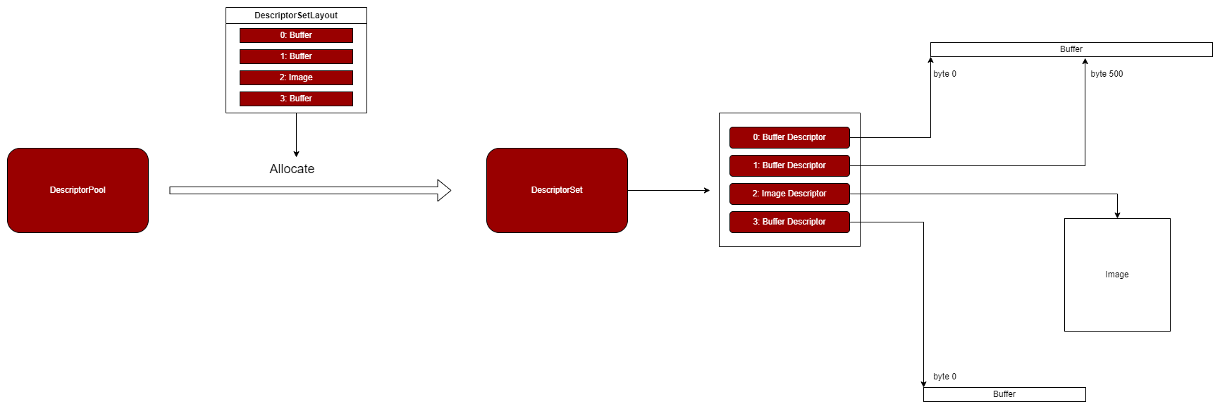
Descriptor Layout
The descriptor layout specifies the types of resources that are going to be accessed by the pipeline. A VkDescriptorSetLayout holds information about the shape of a descriptor set. For example, a possible layout will be one where it binds 2 buffers and 1 image. When creating pipelines or allocating the descriptor sets themselves, you have to use the layout.
- The descriptor set layout describes the shader binding layout (without actually referencing descriptor)
- Like the pipeline layout it’s pretty much a blueprint and can be used with different descriptor sets as long as their layout matches
Descriptor Set
A descriptor set specifies the actual buffer or image resources that will be bound to the descriptors.
- The descriptor set stores the resources bound to the binding points in a shader
- It connects the binding points of the different shaders with the buffers and images used for those bindings
Descriptor Pool
Descriptor sets can’t be created directly, they must be allocated from a pool like command buffers. The equivalent for descriptor sets is unsurprisingly called a descriptor pool.
Alignment requirements
Vulkan expects the data in your structure to be aligned in memory in a specific way, for example:
- Scalars have to be aligned by N (= 4 bytes given 32 bit floats).
- A
vec2must be aligned by 2N (= 8 bytes) - A
vec3or vec4 must be aligned by 4N (= 16 bytes) - A nested structure must be aligned by the base alignment of its members rounded up to a multiple of 16.
- A
mat4matrix must have the same alignment as a vec4.
Uniform buffer
std::vector<VkBuffer> uniformBuffers;
std::vector<VkDeviceMemory> uniformBuffersMemory;
std::vector<void*> uniformBuffersMapped;

void createUniformBuffers() {
    VkDeviceSize bufferSize = sizeof(UniformBufferObject);

    uniformBuffers.resize(MAX_FRAMES_IN_FLIGHT);
    uniformBuffersMemory.resize(MAX_FRAMES_IN_FLIGHT);
    uniformBuffersMapped.resize(MAX_FRAMES_IN_FLIGHT);

    for (size_t i = 0; i < MAX_FRAMES_IN_FLIGHT; i++) {
        createBuffer(bufferSize, VK_BUFFER_USAGE_UNIFORM_BUFFER_BIT, VK_MEMORY_PROPERTY_HOST_VISIBLE_BIT | VK_MEMORY_PROPERTY_HOST_COHERENT_BIT, uniformBuffers[i], uniformBuffersMemory[i]);

        vkMapMemory(device, uniformBuffersMemory[i], 0, bufferSize, 0, &uniformBuffersMapped[i]);
    }
}
The buffer stays mapped to this pointer for the application’s whole lifetime. This technique is called “persistent mapping” and works on all Vulkan implementations. Not having to map the buffer every time we need to update it increases performances, as mapping is not free.
Texture Mapping
Adding a texture to our application will involve the following steps:
- Create an image object backed by device memory
- Fill it with pixels from an image file
- Create an image sampler
- Add a combined image sampler descriptor to sample colors from the texture
Images
Although we could set up the shader to access the pixel values in the buffer, it’s better to use image objects in Vulkan for this purpose. Image objects will make it easier and faster. There are two different concept that may be confusing - tiling and layout. There are two different concept that may be confusing - tiling and layout.
- Image tiling is the addressing layout of texels within an image. This is currently opaque and it is not defined when you access it using the CPU.
- Image layouts are likely (though they don’t have to be) used for internal transparent compression of images when in use by the GPU. This is NOT a lossy block compressed format, it is an internal format that is used by the GPU to save bandwidth! It is unlikely there will be a “standard” compression format that can be exposed to the CPU. The reason you need to transition your images from one layout to another is some hardware may only be able to access the compressed data from certain hardware blocks. source
Image View
Images are accessed through image views rather than directly. We will also need to create such an image view for the texture image.
Sampler
Textures are usually accessed through samplers. It is possible for shaders to read texels directly from images, but that is not very common when they are used as textures.
Add to descriptor set
- Add a
VkDescriptorSetLayoutBindingfor a combined image sampler descriptor. - Bind the actual image and sampler resources to the descriptors in the descriptor set.
- Update Vertex
attributeDescriptions, and addglm::vec2 texCoord;inside struct
Texture Debugging
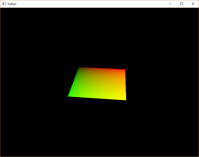
The green channel represents the horizontal coordinates and the red channel the vertical coordinates. The black and yellow corners confirm that the texture coordinates are correctly interpolated from 0, 0 to 1, 1 across the square. Visualizing data using colors is the shader programming equivalent of printf debugging, for lack of a better option!
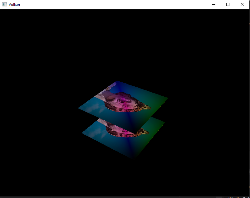
Depth Buffering
Create depth resources: image, memory and image view
A depth attachment is based on an image, just like the color attachment. The difference is that the swap chain will not automatically create depth images for us. We only need a single depth image, because only one draw operation is running at once. Depth Images need to have a reasonable accuracy, at least 24 bits is common in real-world applications. There are several formats that fit this requirement:
VK_FORMAT_D32_SFLOAT: 32-bit float for depthVK_FORMAT_D32_SFLOAT_S8_UINT: 32-bit signed float for depth and 8 bit stencil componentVK_FORMAT_D24_UNORM_S8_UINT: 24-bit float for depth and 8 bit stencil component
VkImage depthImage;
VkDeviceMemory depthImageMemory;
VkImageView depthImageView;- (Optional) Explicitly transitioning the depth image
- Add to Render pass. Create a
VkAttachmentDescriptionfor depth. The format should be the same as the depth image itself. - Modify the framebuffer creation to bind the depth image to the depth attachment.
- Because we now have multiple attachments with VK_ATTACHMENT_LOAD_OP_CLEAR, we also need to specify multiple clear values in
recordCommandBuffer. - Depth and stencil state
VkPipelineDepthStencilStateCreateInfoin graphic pipeline - Handling window resize. Extend the recreateSwapChain function to recreate the depth resources when window is resized.
Loading models
Use the tinyobjloader library to load vertices and faces from an OBJ file.
Mipmaps
Mipmaps are precalculated, downscaled versions of an image. Each new image is half the width and height of the previous one. Mipmaps are used as a form of Level of Detail or LOD. Objects that are far away from the camera will sample their textures from the smaller mip images.
- In Vulkan, each of the mip images is stored in different mip levels of a VkImage. Mip level 0 is the original image, and the mip levels after level 0 are commonly referred to as the mip chain.
Multisampling anti-aliasing (MSAA)
What MSAA does is it uses multiple sample points per pixel (hence the name) to determine its final color.
- Get available sample count from
physicalDeviceProperties - Set up a render target,
VkImage colorImage;VkDeviceMemory colorImageMemory;VkImageView colorImageView; - Add new attachments
pResolveAttachments - Modify createFramebuffers and add the new image view to the list
Misc
What is Attachment?
To understand attachments in Vulkan, You first need to understand render-passes and sub-passes.
Render-pass is a general description of steps Your drawing commands are divided into and of resources used during rendering. We can’t render anything in Vulkan without a render pass. And each render pass must have one or more steps. These steps are called,
Sub-passes and each sub-pass uses a (sub)collection of resources defined for the render-pass. Render-pass’s resources may include render-targets (color, depth/stencil, resolve) and input data (resources that, potentially, were render-targets in previous sub-passes of the same render-pass). And these resources are called,
Attachments (they don’t include descriptors/textures/samplers and buffers).
Why don’t we call them just render-targets or images? Because we not only render into them (input attachments) and because they are only descriptions (meta data). Images that should be used as attachments inside render-passes are provided through framebuffers.
So, in general, we can call them images, because (as far as I know) only images can be used for attachments. But if we want to be fully correct: images are specific Vulkan resources that can be used for many purposes (descriptors/textures, attachments, staging resources); attachments are descriptions of resources used during rendering. source
What is VkSubpassDependency?
VkSubpassDependency specification clarification
Framebuffer
LunarG: Create the Framebuffers
Memory Allocation ???
There are few role of thumb ways to create memory in Vulkan, for example: NV: Vulkan Memory Management and NV: Vulkan Shader Resource Binding It’s good to use the library like Vulkan Memory Allocator to manage your memory in Vulkan
What is binding in VkVertexInputAttributeDescription and VkVertexInputBindingDescription
Stencil test
Source Code
Please check my implementation in here. It include step by step git commit to check the addition for each sub chapther.